| .Introducciůn |
|
La originalidad y lo especŪfico de Avionics REMF es su capacidad de ser a la vez ingenierista, conceptor de sistemas y fabricante de equipos. AIRPORT AUTOMATIC ANSWERING RADIO DEVICE (AARD) /ATIS DRIVER |
|
Avionics REMF estudia cada caso particular de radiocomunicaciůn aeroportuaria y propone soluciones optimales integrando o no sus propios sistemas y equipos. Clicar aquŪ para la pŠgina tťcnica Clicar aquŪ para |
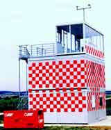
Ejemplo de ingenierŪa torre de control elevadora můvil
|

|
Avionics REMF ha estudiado soluciones de radiocomunicaciůn aeroportuaria en el suelo estŠndar que corresponden a necesidades recurrentes o no en muchos aerůdromos. Los ejemplo de ingenierŪa o de sistemas mŠs abajo muestran de manera no exhaustiva las configuraciones mŠs comunes. |
|
|
Con arreglo a sus actividades en ingenierŪa, Avionics REMF estudia y realiza torres de control můviles y/o provisionales asŪ que la logŪstica asociada y el mantenimiento operacional. Clicar aquŪ para video clip de torres de control provisionales |
Torre de control modular |
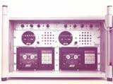
Estaciůn en el suelo emisiůn-recepciůn
ę ŕltimo soccoro Ľ configurado de manera compacta.
|
Estaciůn en el suelo ę ŕltimo soccoro Ľ |
|
En esta foto el pliego de condiciones ha sido establecido por par Avionics REMF despuťs de la estimaciůn de las necesidades del cliente. |
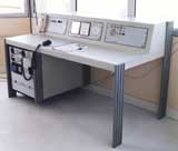
Pupitre de control para puesto de mando |
| Pupitre de control compuesto y adaptable para torres de control můvil o fija, incluyendo las funcionalidades bŠsicas requeridas para los aerůdromos secundarios. |
|
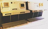
| Este concepto inovante de estaciůn en el suelo con pupitres deportados (tipo SYS 300) permite utilizar un solo emisor-receptor para cada frecuencia y varios puestos operador deportados. |
Estaciůn
en el suelo con pupitres deportados |
| Los equipos presentados mŠs abajo no son una reprsentaciůn exhautiva de la gama aeroportuaria de Avionics REMF. |
|
Emisor-receptor
doble . |
Emisor-receptor
con pupitres deportados
|
pupitres
deportados
|
||||||||||
|
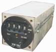
Receptor
de telemando de balisaje |
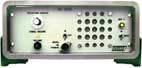
Anunciador
VHF ę ATIS Ľ
|
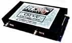
Combinador/separador
VHF/UHF
|
||||||||||
|
Estaciůn
portŠtil VHF |
E/R VHF
por vehŪculo de pista |
Goniometro
por baliza de socorro |
||||||||||
|
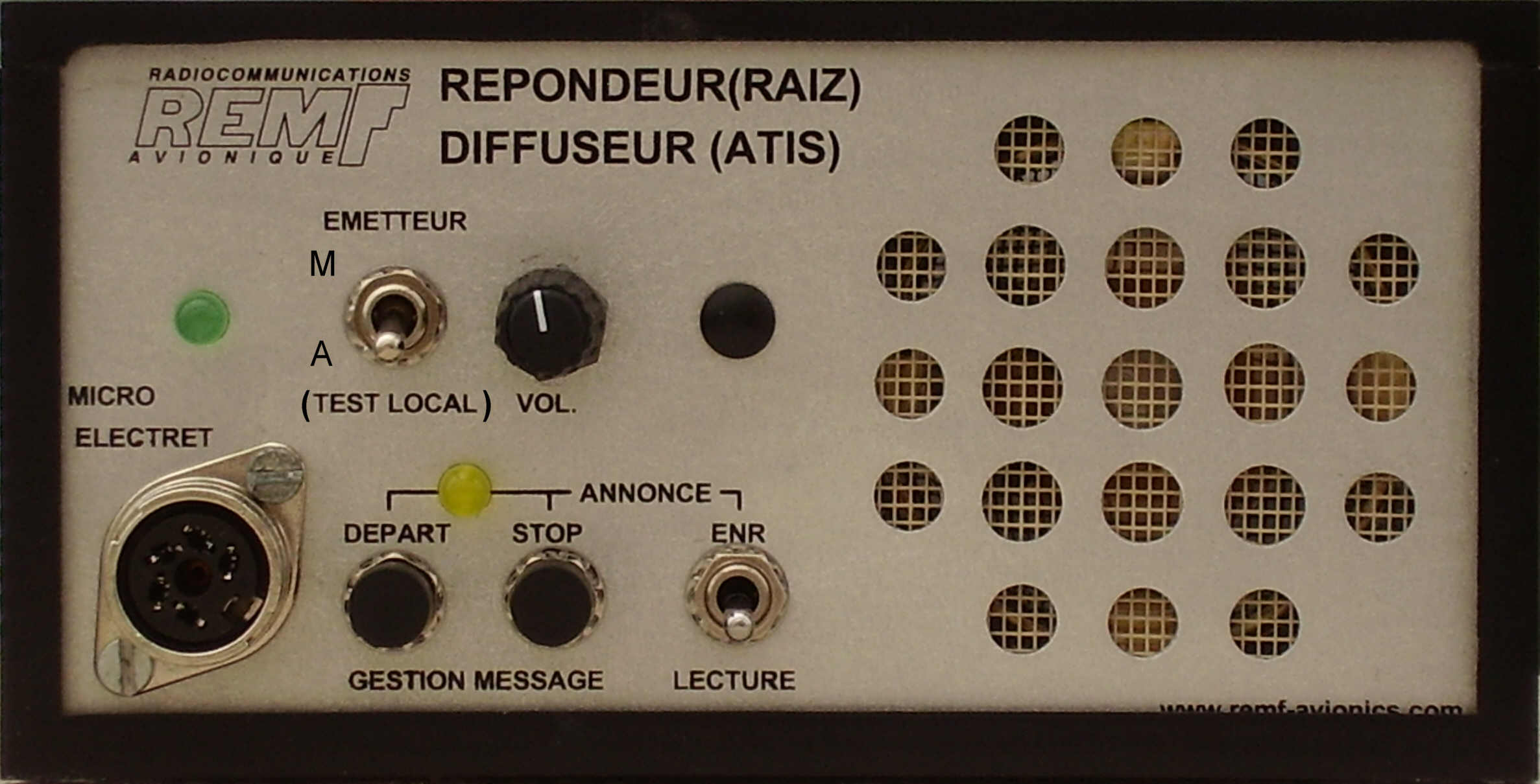
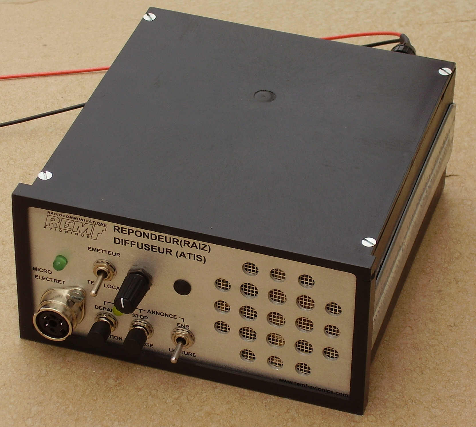
AUTOMATIC ANSWERING RADIO DEVICE (AARD) /ATIS DRIVER (This product can be use also in ďATISĒ function) Drive box built in DIN IEC 61 554 standard instruments enclosure
This device (driver module) is designed to drive external transmitter or built-in stand-alone Answering-transmitter into 19í-2U cabinet to transmit messages (numerically recorded) to aircraft within the aerodrome circuit: - Either in Automatic response from calls of aircraft on the frequency of the airport (Answering mode). - Either by repeating continuously the recorded message on dedicated frequency ("ATIS" broadcast mode). The ATIS mode or Answering (AARD) mode can be factory configured before delivery, or configured by the user (switch). It is also possible to allow the changeover ATIS / AARD mode by the operator (switch on the front or the rear panel of the equipment (to be determined when ordering). When the equipment is fixed as an ATIS or as AARD, marking not useful on the front can be masked by a label). Specific system engineering: design of small towers of fixed and mobile controls towers, control desks and consoles, specific equipment. Manufacturing of Mobile and Modular control towers: "turn-key" System for nonrecurring needs for secondary airports. Systems of radio communication: control desks equipped consoles, sets of radio communication. Standard equipment such as: VHF transceiver ground stations in various cases (19' cabinet, or on desk-table version, fixed and mobile, etc. Specific equipment and products: manufacturing of equipment according to customer request
Recording Time Following the model the term may go 1mn30s to 9 minutes:
Enclosing standard versions
Automatic answering operation in AARD mode There are 3 possibilities:
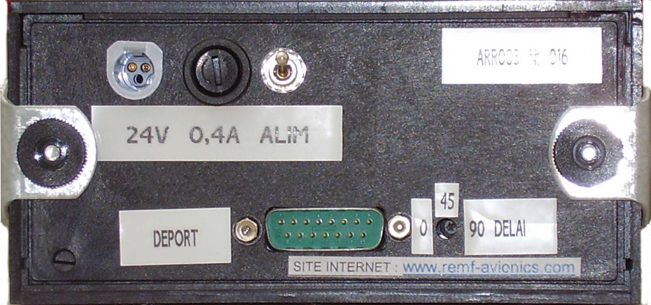
Power supply
Beforehand, the controller records the message to be broadcasted later by the AUTOMATIC ANSWERING RADIO DEVICE (AARD):
A recording stand-by function is controlling by the PPT loystick of the microphone or a by push button on the front panel of the device. The maximum duration of the recorded message is 3 minutes to 9 minutes depending on the version (see above). ANSWERING MODE (AARD):
BROADCAST/ATIS MODE :
The answering machine can replace the controller in his absence. The messages are recorded under the responsibility of the controller. The content of the message can be commercial or informative. The information could not be guaranteed long time after recording is generally prohibited (such as weather parameters, for example) except to indicate explicitly the validity. In any event, it must comply with regulations and practices. For example, information can be: Closing hours of the ATC service, closing for exceptional shortage of fuel, suspension of services on the airport, presence of radio remote control lighting system, runways or taxiways closed, presence of bird, unusable runway, ground clearance, requirement of aircraft call sign, etc ... .
HOW TO USE THE SYSTEM FROM AIRCRAFT There is no technical protocol or special procedure for the pilot. This system answers "naturally" as soon as the pilot finished talking and releasing the PTT of his microphone. At the end of the response of AARD, this last device drives the system for the receiver returns immediately in listening position. To avoid duplication of responses too closely (several aircraft in the circuit), a time limit the responses by an interval of non-response set from 1 to 90 s. This solution allows managing a ďblankĒ after each response to the pilots ensure their safety on the operation frequency channel. FROM ATC CONTROLLERProcedure: Power up the equipment
Recording
Recording stand-by:
End of the recording:
Recording check:
Erasing:
AARD setting for operation (Transmitting validated): Initial precautions:
On the AARD:
Getting OFF of the automatic answering machine (transmitting not allowed): On the AARD:
Setting ON AARD (Transmitting validated): On the AARD:
ATIS MODE (Permanent broadcasted message in loop) Prerequisite:
Power up the equipment:
Recording:
Record stand-by:
End of recording:
Recording checking:
Erasing the message:
Activation of the ATIS (transmitting validated for normal operation): Prerequisite:
Operation:
Setting off of the automatic answering machine (transmit not allowed ďon airĒ):
(Re) Activation of the ATIS (Emission validated):
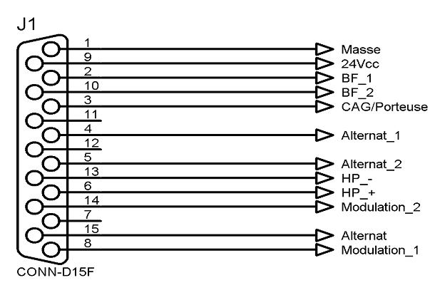
INTERCONNECTIONS INTERCONNECTIONS In answering mode, it is possible to detect calls using the signal detection carrier (preferably) or if it is not available the audio signal reception detection. There is the possibility to use the PTT control by direct connection to ground or by ďfloatingĒ independent contact (preferable to the alternate remote commands, to avoid ground interference currents). The audio input and output are balanced and isolated from the ground (input or output trough a balanced audio transformer). Pin out:
POWER SUPPLY
REMF - ZAC GAROSSOS BP40071 31700 BEAUZELLE (near Toulouse Blagnac International airport ) FRANCE Ph : (33) 5 61 59 93 37 Fax : (33) 5 61 59 33 85 WEB SITE www.remf-avionics.com E-mail : contact@remf-avionics.com
|
||||||||||||


|
Nuestra capacidad de innovaciůn supo seducir a muchos clientes en el mundo : AlemaŮa, Bťlgica, Burkina Faso, Costa de marfil, EspaŮa, Francia, Gabůn, Inglaterra, Guatemala, Islas Fidji, Italia, Marruecos, Senegal, Suiza, Tķnez, EtcÖ. |
| Avionics
REMF Aviůnica - Radiocomunicaciones aeroportuaria - Defensa ZAC Garossos - Rue du Juncassa - 31700 Beauzelle - France Telefono : +33 (0)5 61 59 93 37 - Fax : via: E-mail : contact@remf-avionics.com |


